Mass Transfer Columns
Contents
- 1 Multi-Stage Process Blocks
- 2 Distillation/Stripper Unit
- 3 Data Requirements
- 4 Column Parameters
- 5 Column Configuration
- 6 Guidelines
- 7 Absorber Unit
- 8 Data Requirement
- 9 Column Parameters
- 10 Column Configuration
- 11 Guidelines
- 12 Extractor Unit
- 13 Data Requirement
- 14 Column Parameters
- 15 Column Configuration
- 16 Guidelines
- 17 References
Multi-Stage Process Blocks
This section contains detailed specification requirements for multi-stage process blocks available in ESP. Generally, these process units are columns/towers. The process units available are:
- Stripper
- Absorber
- Extractor
The unit to be specified is selected from the display using the Arrow Keys and then the Enter Key.
Additional column specification facilities are available via the Action Key and then by selecting the Parameters and Config facilities. These facilities are detailed for each individual unit.
Distillation/Stripper Unit
This is a multi-stage conventional or environmental unit allowing species in a liquid to be separated either by distillation, or by the action of a countercurrent vapor stream (i.e., stripper). The unit can hold a maximum of 50 stages, 10 feed streams, and 10 exit streams.
When this block is selected the user can choose either an electrolyte column or a non-electrolyte column (if a non-electrolyte model was created). In the case of an electrolyte column, an aqueous phase must be present in every liquid stream. The liquid feed and/or liquid product can contain both an aqueous and nonaqueous liquid phase, and just an aqueous phase alone. In the case of a non-electrolyte column, only the non-electrolyte liquid phase exists (electrolyte chemistry is not considered).
When this block is selected the user is forced to choose either a standard column or a mass transfer limited column. The standard column applies for the rigorous equilibrium model which is based on the component material balance, energy balance and thermodynamic correlations and criteria of phase equilibria at each stage; however, the mass transfer limited column applies for the nonequilibrium model, which explicitly accounts for mass and heat transfer except material and energy balance and phase equilibria. Therefore, the mass transfer limited column may provide more realistic concentration and temperature profile through the column. In the mass transfer limited column, each stage is divided into five parts: vapor bulk, vapor film, vapor/liquid interface, liquid film and liquid bulk; the mass-transfer and heat-transfer resistances are assumed to lie in two thin film layers that are separated by the vapor/liquid interface; at the interface, the vapor and the liquid are in equilibrium.
The unit may be set to a single stage standard or mass transfer limited column without condenser and reboilor.
Data Requirements
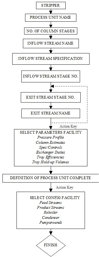
A minimum of one feed stream and two exit streams (i.e., distillate and bottoms) must be named when using the unit for distillation. An additional feed must be added when using the unit as a stripper. The feed stream temperature, pressure, flow and composition data must be specified by the user or be a product stream from another Process Block. The number of stages will default to 10 and appear that way on the initial screen. The user may override this value. If there is a condenser or reboiler, these will count as stages. Additionally, various column operating parameter information must be supplied by the user.
Column Parameters
The column operating parameters are accessed using the Action Key and then by selecting the Parameters facility. Nine options are available for the standard column:
Pressure Profile This option allows an accurate pressure profile to be specified. This is done by specifying top and bottom stage pressures, taking the reboiler and condenser into account. If only one stage pressure is given, a zero pressure drop through the column is assumed. If no values are given, the entire column is assumed to operate at atmospheric pressure. Column Estimates This option allows stage operating temperatures, vapor distillate and liquid reflux flow estimates to be specified. The estimates for top and bottom stage temperature, as well as the vapor distillate rate and liquid reflux flowrates, must all be specified by the user. The Esc Key is used to change displays.
Spec/Controls This function is optional and allows the user to manipulate parameters (e.g., heat exchanger duty) to meet specifications in the column operation. For example, vapor and/or liquid composition specifications, stage operating temperature, and vapor and/or liquid stream flowrate specifications can all be achieved.
Exchanger Duties This option allows column and pump-around heat exchanger duties to be specified. For columns using a condenser and/or reboiler, the user must define duties for the respective units. Negative heat duties imply heat removal. The End Key returns the user to the process block display.
Tray Efficiencies This function is optional and allows the user to specify Murphree efficiencies for the column stages. If no data is entered, the stage efficiency is assumed to be 1.0. The End Key returns the user to the process block display. This function is not available for mass transfer limited columns.
Component Efficiencies This function is optional and allows the user to specify Murphree efficiencies for individual components in each column stage. If no data is entered, the efficiency for individual component is assumed to be 1.0. The End Key returns the user to the process block display. This function is not available for mass transfer limited columns.
Convergence Parameters This function is optional and allows the user to specify the Maximum number of iteration and convergence tolerance and if initialize column each time in recycle loops. If no data is entered, the Maximum number of iteration is assumed to be 35, the convergence tolerance is assumed to 5.0E-7 and column has no initialization each time in recycle loops. The End Key returns the user to the process block display.
Tray Hold-Up Time This function is required for columns whose chemistry contains rate-limited reactions. This facility allows the user to specify both liquid and vapor hold-up volumes for specific column stages. The End Key changes the display and returns the user to the process block display.
Condenser Type This function is optional and allows the user to specify the type of condenser. If no data is entered, the condenser is assumed to be partial condenser. The End Key returns the user to the process block display.
Except those options above, there are three more options available for the mass transfer limited column:
Mass Transfer Parm This option allows the user to specify vapor-liquid mass and heat transfer coefficients on each stage of the column. The coefficients are overall coefficients and apply to all components. The interfacial transfer area must also be specified. If the same coefficients are used throughout the column, the coefficient may be varied to meet a composition specification by means of the spec/control parameters. The End Key returns the user to the process block display. If the mass and heat transfer coefficients are not specified by the user, then the software will calculate them based on column type the user chooses.
Column Type This option allows the user to specify column type and the specific parameters. There are four column types available: Packed column, Sieve Tray and Bubble Cup and Valve Tray. The End Key returns the user to the process block display. Since one of the transport properties, surface tension is not available in OLI Engine, they are set to be constant (0.07kg/s) in the column calculations. For packed column, the user is allowed to specify the height of stage, column diameter, column packing type, column packing material, and column packing size [1]; For sieve tray column [2], the user could set the column diameter, weir height, froth height and clear liquid height; for bubble cap column [3], column diameter is available to be specified by the user; for valve tray data [4], column diameter and weir height could be specified. The Chilton-Colburn analogy has been applied to correlate the heat transfer coefficient with mass transfer coefficient for species [5]. The method of Mathur et al (1967) has been adopted to calculate the overall heat transfer coefficients [6]. The users also could define their own column type by a user-defined subroutine.
Interface Film Type This function is optional and allows the user to specify the number of liquid interface film segments. The default value is 1. If a value more than 1 is set (N=1-10), the film discretization method is applied to calculate the concentration profile in the liquid film region. This approach is applied to take into account the possible influence of ionic interaction on the species mass transfer in the liquid film. In this approach, the liquid film is further divided into N films and the Nernst-Planck equation and Poisson equation are used to describe the electrolyte fluid in the liquid film. The user can choose to use the film discretization method by specifying the number of films (regular mass transfer limited column if the number of film is set to 1). [7-8].
Column Configuration
Additional column parameters can be defined, via the Action Key, and selecting the Config facility. Five options are available:
Feed Streams This function is optional and allows the user to specify up to 8 additional feed streams to the column.
Product Stream This function is optional and allows the user to specify up to 8 additional product streams from the column.
Condenser/Reboiler This option allows the user to delete, or insert, these respective units from/to the column. Initially, the process block includes the two units on the display.
Pump-arounds This function is optional and allows the user to specify side stream pumparounds if required. Pumparounds must be from a lower to a higher stage of the column and the flowrate must be defined.
Guidelines
1. When defining feed stream compositions and column operating parameters the Enter Key must be pressed after every data entry, even if it is zero. If this is not performed the data entry is not saved.
2. For columns with condenser and/or reboiler units the heat duty estimates defined by the user must be such that a vapor flow exists on the bottom stage and a liquid phase flow exists on the top stage of the column respectively.
3. The column can only operate if two (or optionally three) phases exist on every stage of the column.
4. For columns without a condenser and/or reboiler unit, a feed stream must be specified entering at the respective position of the omitted unit. The phase of this stream must be correctly defined. A liquid phase feed stream is required as an alternative to a column condenser, and a vapor phase stream in place of a reboiler unit (i.e., the column must have two phases flowing to and from every stage).
5. When defining a stripper unit, an all liquid feed stream must be specified entering the top of the column and the stripping vapor must enter the bottom of the unit.
6. When defining stripper column parameters, a zero liquid reflux (i.e., distillate) flow must be made. This is because the distillate flow exiting the unit must only exist in the vapor phase.
7. All column stages are numbered from bottom to top.
8. If a feed stream contains both a vapor and a liquid phase, the liquid goes to the feed tray specified by the user and the vapor goes to the stage above.
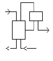
Figure 2-8 Distillation/Stripper Schematic
Absorber Unit
This is a multi-stage conventional or environmental process unit which allows species in a vapor feed to be absorbed by a countercurrent liquid stream. The unit can hold up to a maximum of 50 stages and up to a maximum of 10 feed and 10 product streams.
When this block is selected the user can choose either an electrolyte column or a non-electrolyte column (if a non-electrolyte model was created). In the case of an electrolyte column, an aqueous phase must be present in every liquid stream. The liquid feed and/or liquid product can contain both an aqueous and nonaqueous liquid phase or just an aqueous phase alone. In the case of a non-electrolyte column, there is only the non-electrolyte liquid phase (electrolyte chemistry is not considered).
When this block is selected the user is forced to choose either a standard column or a mass transfer limited column. The standard column applies for the rigorous equilibrium model which is based on the component material balance, energy balance and thermodynamic correlations and criteria of phase equilibria at each stage; however, the mass transfer limited column applies for the nonequilibrium model, which explicitly accounts for mass and heat transfer except material and energy balance and phase equilibria. Therefore, the mass transfer limited column may provide more realistic concentration and temperature profile through the column. In the mass transfer limited column, each stage is divided into five parts: vapor bulk, vapor film, vapor/liquid interface, liquid film and liquid bulk; the mass-transfer and heat-transfer resistances are assumed to lie in two thin film layers that are separated by the vapor/liquid interface; at the interface, the vapor and the liquid are in equilibrium.
The unit may be set to a single stage standard or mass transfer limited column without condenser and reboilor.
Data Requirement
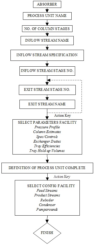
A minimum of one liquid stream entering the top of the column and one vapor stream entering the bottom of the unit must be specified. The respective feed stream temperature, pressure, flow and composition must be defined by the user or be a product stream from another Process Block.
When defining the feed stream, the temperature and pressures of each stream should be such that the species components reside in the correct phase for the respective stream.
The column exit vapor and liquid streams must be named, in addition to various column parameters.
Column Parameters
The column operating parameters are accessed using the Action Key and selecting the Parameters facility. The column operating parameters are accessed using the Action Key and then by selecting the Parameters facility. Nine options are available for the standard column:
Pressure Profile This option allows an accurate pressure profile to be specified. This is done by specifying top and bottom stage pressures, taking the reboiler and condenser into account. If only one stage pressure is given, a zero pressure drop through the column is assumed. If no values are given, the entire column is assumed to operate at atmospheric pressure.
Column Estimates This option allows stage operating temperatures, vapor distillate and liquid reflux flow estimates to be specified. The estimates for top and bottom stage temperature, as well as the vapor distillate rate and liquid reflux flowrates, must all be specified by the user. The Esc Key is used to change displays.
Spec/Controls This function is optional and allows the user to manipulate parameters (e.g., heat exchanger duty) to meet specifications in the column operation. For example, vapor and/or liquid composition specifications, stage operating temperature, and vapor and/or liquid stream flowrate specifications can all be achieved.
Exchanger Duties This option allows column and pumparound heat exchanger duties to be specified. For columns using a condenser and/or reboiler, the user must define duties for the respective units. Negative heat duties imply heat removal. The End Key returns the user to the process block display.
Tray Efficiencies This function is optional and allows the user to specify Murphree efficiencies for the column stages. If no data is entered, the stage efficiency is assumed to be 1.0. The End Key returns the user to the process block display. This function is not available for mass transfer limited columns.
Component Efficiencies This function is optional and allows the user to specify Murphree efficiencies for individual components in each column stage. If no data is entered, the efficiency for individual component is assumed to be 1.0. The End Key returns the user to the process block display. This function is not available for mass transfer limited columns.
Convergence Parameters This function is optional and allows the user to specify the Maximum number of iteration and convergence tolerance and if initialize column each time in recycle loops. If no data is entered, the Maximum number of iteration is assumed to be 35, the convergence tolerance is assumed to 5.0E-7 and column has no initialization each time in recycle loops. The End Key returns the user to the process block display.
Tray Hold-Up Time This function is required for columns whose chemistry contains rate-limited reactions. This facility allows the user to specify both liquid and vapor hold-up volumes for specific column stages. The End Key changes the display and returns the user to the process block display.
Condenser Type This function is optional and allows the user to specify the type of condenser. If no data is entered, the condenser is assumed to be partial condenser. The End Key returns the user to the process block display.
Except those options above, there are three more options available for the mass transfer limited column:
Mass Transfer Parm This option allows the user to specify vapor-liquid mass and heat transfer coefficients on each stage of the column. The coefficients are overall coefficients and apply to all components. The interfacial transfer area must also be specified. If the same coefficients are used throughout the column, the coefficient may be varied to meet a composition specification by means of the spec/control parameters. The End Key returns the user to the process block display. If the mass and heat transfer coefficients are not specified by the user, then the software will calculate them based on column type the user chooses.
Column Type This option allows the user to specify column type and the specific parameters. There are four column types available: Packed column, Sieve Tray and Bubble Cup and Valve Tray. The End Key returns the user to the process block display. Since one of the transport properties, surface tension is not available in OLI Engine, they are set to be constant (0.07kg/s) in the column calculations. For packed column, the user is allowed to specify the height of stage, column diameter, column packing type, column packing material, and column packing size [1]; For sieve tray column [2], the user could set the column diameter, weir height, froth height and clear liquid height; for bubble cap column [3], column diameter is available to be specified by the user; for valve tray data [4], column diameter and weir height could be specified. The Chilton-Colburn analogy has been applied to correlate the heat transfer coefficient with mass transfer coefficient for species [5]. The method of Mathur et al (1967) has been adopted to calculate the overall heat transfer coefficients [6]. The users also could define their own column type by a user-defined subroutine.
Interface Film Type This function is optional and allows the user to specify the number of liquid interface film segments. The default value is 1. If a value more than 1 is set (N=1-10), the film discretization method is applied to calculate the concentration profile in the liquid film region. This approach is applied to take into account the possible influence of ionic interaction on the species mass transfer in the liquid film. In this approach, the liquid film is further divided into N films and the Nernst-Planck equation and Poisson equation are used to describe the electrolyte fluid in the liquid film. The user can choose to use the film discretization method by specifying the number of films (regular mass transfer limited column if the number of film is set to 1). [7-8].
Column Configuration
Additional column parameters can be defined, via the Action Key and selecting the Config facility. Five options are available:
Feed Streams This function is optional and allows the user to specify up to 8 additional feed streams to the column.
Product Stream This function is optional and allows the user to specify up to 8 additional product streams from the column.
Condenser/Reboiler This option allows the user to delete, or insert, these respective units from/to the column. Initially, the process block does not include the two heat exchanger units.
Pumparounds This function is optional and allows the user to specify side stream pumparounds if required. Pumparounds must be from a lower to a higher stage of the column and the flowrate must be defined.
Guidelines
1. When defining feed stream compositions and column operating parameters the Enter Key must be pressed after every data entry, even if it is zero. If this is not performed the data entry is not saved.
2. When defining column parameters a zero liquid reflux (i.e., distillate) rate should be defined. This is because the distillate flow exiting the unit must only exist in the vapor phase.
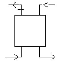
Figure 2-9 Absorber Schematic
Extractor Unit
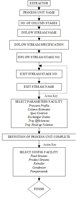
This is a multi-stage conventional or environmental process unit which allows countercurrent liquid-liquid extraction to be simulated. The unit can hold a maximum of 50 stages, 10 feed and 10 exit streams.
When this block is selected, the user can choose either an electrolyte column or a non-electrolyte column (if a non-electrolyte model was created). In the case of an electrolyte column, one of the two liquid streams is aqueous. In the case of a non-electrolyte column, both liquid streams are nonaqueous (electrolyte chemistry is not considered).
This unit does not support the mass transfer limited model and single stage functionality.
Data Requirement
A minimum of one aqueous feed stream must be defined entering the top of the column, and the solvent stream entering the bottom of the unit. The respective feed streams temperatures, pressures, flows and compositions must be specified, or be a product stream from another Process Block, and the unit outflows named. Additionally, various column operating parameter information must be specified by the user.
Column Parameters
The column operating parameters are accessed using the Action Key and selecting the Parameters facility. The column operating parameters are accessed using the Action Key and selecting the Parameters facility. The column operating parameters are accessed using the Action Key and then by selecting the Parameters facility. Nine options are available for the standard column:
Pressure Profile This option allows an accurate pressure profile to be specified. This is done by specifying top and bottom stage pressures, taking the reboiler and condenser into account. If only one stage pressure is given, a zero pressure drop through the column is assumed. If no values are given, the entire column is assumed to operate at atmospheric pressure.
Column Estimates This option allows stage operating temperatures, vapor distillate and liquid reflux flow estimates to be specified. The estimates for top and bottom stage temperature, as well as the vapor distillate rate and liquid reflux flowrates, must all be specified by the user. The Esc Key is used to change displays.
Spec/Controls This function is optional and allows the user to manipulate parameters (e.g., heat exchanger duty) to meet specifications in the column operation. For example, vapor and/or liquid composition specifications, stage operating temperature, and vapor and/or liquid stream flowrate specifications can all be achieved.
Exchanger Duties This option allows column and pumparound heat exchanger duties to be specified. For columns using a condenser and/or reboiler, the user must define duties for the respective units. Negative heat duties imply heat removal. The End Key returns the user to the process block display.
Tray Efficiencies This function is optional and allows the user to specify Murphree efficiencies for the column stages. If no data is entered, the stage efficiency is assumed to be 1.0. The End Key returns the user to the process block display. This function is not available for mass transfer limited columns.
Component Efficiencies This function is optional and allows the user to specify Murphree efficiencies for individual components in each column stage. If no data is entered, the efficiency for individual component is assumed to be 1.0. The End Key returns the user to the process block display. This function is not available for mass transfer limited columns.
Convergence Parameters This function is optional and allows the user to specify the Maximum number of iteration and convergence tolerance and if initialize column each time in recycle loops. If no data is entered, the Maximum number of iteration is assumed to be 35, the convergence tolerance is assumed to 5.0E-7 and column has no initialization each time in recycle loops. The End Key returns the user to the process block display.
Tray Hold-Up Time This function is required for columns whose chemistry contains rate-limited reactions. This facility allows the user to specify both liquid and vapor hold-up volumes for specific column stages. The End Key changes the display and returns the user to the process block display.
Condenser Type This function is optional and allows the user to specify the type of condenser. If no data is entered, the condenser is assumed to be partial condenser. The End Key returns the user to the process block display.
Column Configuration
Additional column parameters can be defined, via the Action Key and selecting the Config facility. Five options are available:
Feed Streams This function is optional and allows the user to specify up to 8 additional feed streams to the column.
Product Stream This function is optional and allows the user to specify up to 8 additional product streams from the column.
Condenser/Reboiler This option allows the user to delete, or insert, these respective units from/to the column. Initially, the process block does not include the two heat exchanger units on the display.
Pumparounds This function is optional and allows the user to specify side stream pumparounds if required. Pumparounds must be from a lower to a higher stage of the column and the flowrate must be defined.
Guidelines
1. When defining feed stream compositions and column operating parameters the Enter Key must be pressed after every data entry, even if it is zero. If this is not performed the data entry is not saved.
2. The feed stream conditions must be specified such that no vapor phase species exist in the streams or the column.
3. When specifying column flowrates exiting the top stage, the organic phase stream is defined as the vapor distillate flowrate.
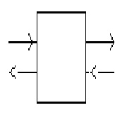
Figure 2-10 Extractor Schematic
References
[1] Billet, R., Schulte's, M. Trans. IchemE. , 77, 498-504 1999.
[2] Moniuk W.; Hungarian; Journal of Industrial Chemistry. Vol. 17; 93-105 1989
[3] Akita K and Yoshida F.; Ind. Eng. Chem. Process Des. Develop. Vol. 12 No. 1 1973
[4] Scheffe and WeilandInd., Eng. Chem. Res. 1987, 26, 228-236
[5] Chilton T. H. and Colburn A.P., Ind. Engng Chem. 1934 26, 1183
[6] Mathur S. Tondon P.K. and Saxena S.C.; Molecular Physics 1967 12 569
[7] Taylor R., Krishna R., Multicomponent mass transfer, 1993, Wiley, New York
[8] Mafe R., Pellicer J. and Aguilelia V. M. Journal of Computational Physics 75, 1-14, 1988
This was former Tip81.
