Difference between revisions of "Flue Gas Scrubbing"
| Line 23: | Line 23: | ||
[[File:Flue Gas Output.jpg]] | [[File:Flue Gas Output.jpg]] | ||
| + | |||
| + | |||
| + | [[Categories: Applications]] | ||
Revision as of 21:04, 15 October 2014
Flue Gas Scrubbing
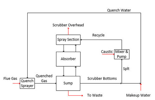
Flue gas scrubbers remove HCl, SOx NOx, and other strong acids from combustion gases. The diagram below is a basic schematic showing the process flow.
Hot combustion gas enters the quench sprayer where quench water dissolves strong-acid gases; HCl, NO3, and SO3. The gas flows into the tower where the caustic solution removes the weak acid; SO2 and in some cases CO2. The Caustic recycle pH is controlled so that the system can remove SO2 and CO2 or only SO2. There are two waste streams, one containing the strong acids and the other a slack blowdown stream which will can go to an SO2 oxidizer and/or to a CO2 concentrator.
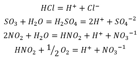
=+=Chemical Mechanisms==+ The two types of acid-gas reactions are shown below. The first set is the reactive gases that form strong acids. The reactions for NOx follows several steps, includes O2 oxidation of NO to NO3(-1).
The second set of equations are for the reactive gases that form weak acids in water.
There are several bases available for this system, we will use NaOH in the simulation.
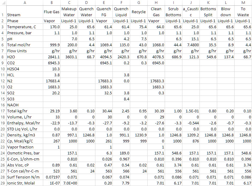
Process Simulation
The flow schematic above is used in OLI ESP to compute steady state conditions. The table below contains the gas-phase composition, the makeup water and caustic, and the blowdown streams. The example case is prepared and ready to be optimized to minimize makeup water and caustic addition.


