Benfield process
Benfield Process
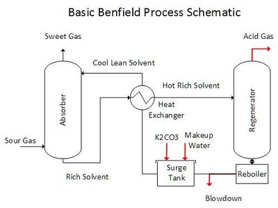
The Benfield Process is a technique used to remove the acid-gases, CO2 and H2S from petroleum and industrial gases. The image below is a generalized Benfield Process schematic.
The process contains a gas absorption step and an carbonate regeneration step. Potassium carbonate (K2CO3) is the alkali in the absorption solvent. K2CO3 reacts with CO2 and H2S in the Absorber tower forming bicarbonate (HCO3-1) and bisulfide (HS-1). This reaction enables the solvent to dissolve significantly more CO2 and H2S than is possible with pure water. The spent solvent is steam stripped of the absorbed CO2 and H2S in the Regeneration tower. The regenerated solvent is recycled back to the absorber after energy recovery using heat exchangers.
Chemical Mechanism in the Absorber and Regenerator
The chemical reactions between the acid gases and K2CO3 are well known,
These reactions are reversible. They proceed from left to right in the Absorber unit and from right to left in the Regeneration unit.
Steady-state processing
Ideal mass balance is achieved when the CO2 and H2S moles absorbed from the Sour Gas equals the CO2 and H2S moles exiting with the Acid Gas. Deviation from ideal mass balance will occur if CO2, H2S, and also H2O absorption or removal are out of balance. Furthermore, impurity entering with the Sour Gas will buildup in the alkali solvent if they cannot be removed as a vapor. Thus, a blowdown stream is used to maintain consistent solvent properties. A makeup H2O stream maintains a steady state recycle flow rate (actually sump tank level in field applications). Also, a makeup K2CO3 stream maintains a steady-state free carbonate or pH level in the lean solvent.
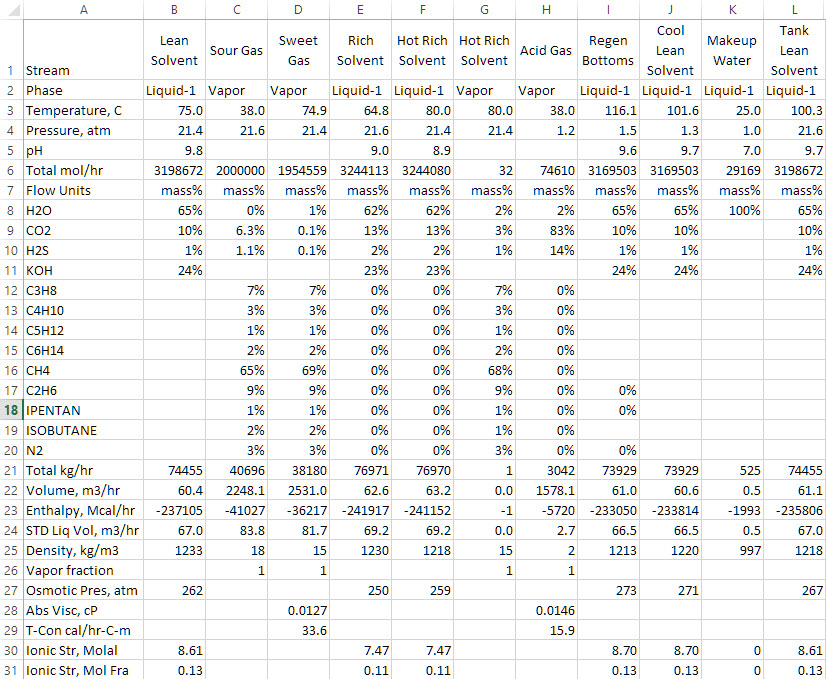
Below is a steady-state output of the Benfield Simulation performed using ESP Original


